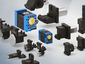
MODULAR SYSTEM - FUNCTIONS
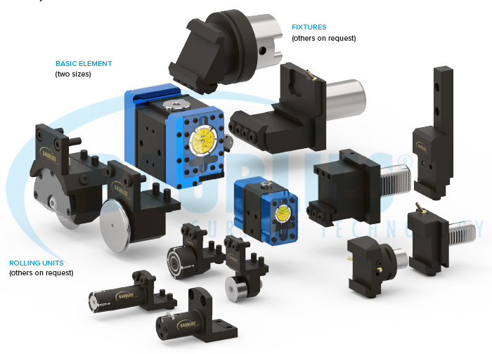
FIXTURE
The fixture represents the connection between machine and tool. The basic element is connected by a form-closed clamping bar to the tool fixture.
ROLLING UNIT
The rolling unit guides and supports the roll and is connected to the fixture and the basic element. It is optimally adapted to the processing task. The rolling unit is connected with four screws to the basic element.
BASIC ELEMENT
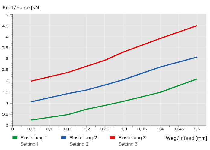
The basic element contains the spring of the single-roller tool. This spring enables you to define the rolling force in dependence to the tool preload. The rolling force can be determined by using the chart. If the exact value of the force is required, the optionally available testing device has to be used.
Please note:
Optional Path indicator housing on both sides is available.
MODULAR SYSTEM - BASIC ELEMENT
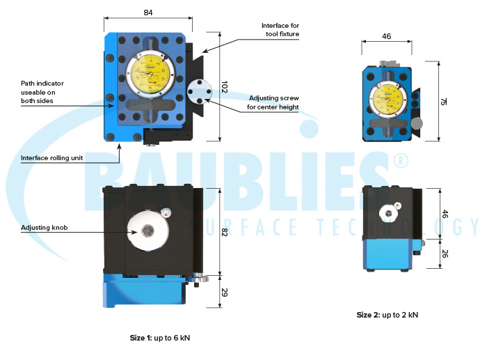
BASIC ELEMENT MODULAR SINGLE_ROLLER TOOL SYSTEM
The basic element is available in two sizes. The machining direction (internal/external) and the tool preload is set by an adjusting knob.
ADVANTAGES
- Easy to use
- Adjustable tool preload
- Rugged tool design
MODULAR SYSTEM - TESTING DEVICE
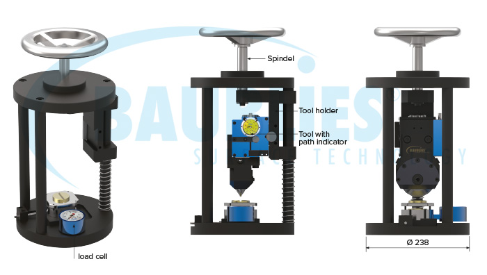
Properties testing device
The test device is used to set and to check the required tool preload characteristics. With the path indicator and the load cell it is then possible to correlate the tool preclamp with the rolling force to support constant process parameters.
ADVANTAGES
- Easy to use
- Rugged design
- Including certified hydraulic load cell
- Useable for diverse tool types
TOOL ASSEMBLY AND HANDLING
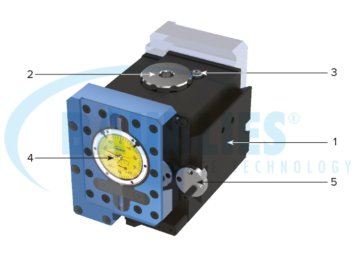
1 Basic element
2 Adjusting knob with spring
3 Locking screw
4 Path indicator
5 Adjusting screw for center height
CHANGE PRELOAD OF THE TOOL
Remove the locking screw (3). Set the preload of the spring by turning the adjusting knob (2).
Turn clockwise
= preload increases
Turn counterclockwise
= preload decreases
The preload of the spring can be checked with the optional test device. Reassemble locking screw (3).
ADJUSTING THE CENTER HEIGHT
Loosen the clamping of the tool fixture. The center height is adjusted by the adjusting screw (5). The setting should be up to 1 mm above the machining center line. Fix the clamping of the tool fixture.
TIP
- The preload of the tool during burnishing should be in a range between 0.1 and 0.5 mm.
- Always work with cooling and avoid interrupted cuts.
- The path indicator helps to set up the tool, especially when using conventional machines.
- Due to the occurance of high rolling forces, it is important to ensure sufficient clamping of the workpiece and tool.